DrFuel / catalogue reference
Fuel Pump Comparison: Walbro 460 vs 525 vs 535 vs BPC100 vs BPC100 + 535 (AI-SSR25)
Compare Walbro 460, 525, 535 and BPC100 + BKS1001 / E5LM catalogue performance at 12–16 V supply. The fifth option stages the 535 off below 11 V DC-equivalent and adds it at 11 V and above. The 11–12 V band is extrapolated: a comparison estimate, not verified linked-PWM performance.
Loading interactive comparison…
Loading pump setup controls…
Pump selections, quantities and operating-point controls will appear when the interactive comparison is ready.
Loading shared voltage, pressure and command controls…
Loading comparison chart…
Flow and current views loadingCompare Walbro 460, 525, 535 and BPC100 + BKS1001 / E5LM catalogue performance at 12–16 V supply. The fifth option stages the 535 off below 11 V DC-equivalent and adds it at 11 V and above. The 11–12 V band is extrapolated: a comparison estimate, not verified linked-PWM performance.
The interactive comparison loads with JavaScript. Duty Cycle (PWM) runs from 50–100%: brushed SSR duty is unscaled; BPC100 uses displayed command × 0.9, so 100% display corresponds to 90% actual BPC PWM and 1,100 LPH nominal flow, not SPEED-dial mode. Linked controls apply one displayed setting; independent controls retain separate settings, including separate BPC100 and 535 channels in the combined setup. Reduced-duty brushed results are ideal estimates; only 11–12 V equivalent is extrapolated from existing 12 V and 13.5 V curves, not measured PWM performance. The combined setup stages its 535 off below 11 V equivalent according to the 535's own duty and shows its BPC100 component alone; this overlaps the standalone BPC100 curve only when their commands match. This model floor is not a safe physical cutoff. Source provenance, assumptions and current boundaries are explained below.
Aftermarket Industries · PWM solid-state relay
AI-SSR25 PWM fuel pump control
Use an AI-SSR25 to switch the supply to a suitable brushed fuel pump from a compatible ECU PWM output. It is a solid-state relay, not a voltage booster.
- PWM-capable solid-state switching
- One AI-SSR25 per fuel pump
- Control from a compatible ECU PWM output
Suitability. Check each pump’s peak current, including startup/inrush and worst-case operating conditions, against the relay’s ratings. Confirm cooling requirements and ECU signal compatibility before choosing a setup.
Comparison limit. The BPC100 + 535 comparison is a staged estimate, not verified linked-PWM performance: the 535 is staged off below 11 V DC-equivalent and added at or above 11 V. Standalone SSR-equipped setups use the same model. The 11–12 V band is extrapolated from existing 12 V and 13.5 V curves, not measured AI-SSR25 performance or a safe operating cutoff. Relay losses and peak/startup current are not modelled.
View AI-SSR25 product details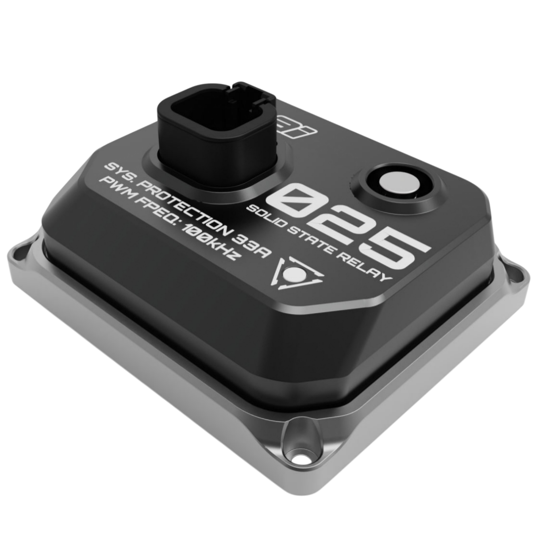
Fuel pump comparison questions
How do I compare the Walbro 460, 525 and 535?
Compare the same supply voltage, pressure and pump quantity rather than advertised litres-per-hour names alone. This page uses the existing Components data for F90000274 (460), F90000285 (525) and F90000295 (535). Part numbers matter: similarly named pump variants should not automatically be treated as identical.
How much current do these Walbro fuel pumps draw?
Current depends on the specific pump, supply voltage and pressure. Without an SSR attachment, Walbro figures are pump-only DC current; BPC100 figures are controller input current. With an optional AI-SSR25 attachment on a standalone brushed setup, the tool estimates DC-equivalent pump-side current using supply voltage × duty/100 and existing DC curves. That ideal estimate is not measured PWM or battery/input current, excludes relay/ripple losses, and becomes unavailable outside the source data. These measurement boundaries are not equivalent; check peak/startup current and ECU compatibility separately.
Can I compare dual and triple Walbro fuel pumps?
Yes. Select one, two or three identical 460, 525 or 535 pumps. The comparison adds their source flow and current at the same voltage and pressure as ideal parallel sums. Shared plumbing, filters, regulators and wiring can reduce real delivery; the totals are not a guarantee of installed performance.
Why is the BPC100 flow curve flat while its current changes?
The BPC100 plot represents nominal regulated-flow command, not a measured maximum-flow curve. The displayed 50–100% control is normalized: multiply by 0.9 to obtain actual BPC100 PWM. Displayed 100% therefore commands 90% actual PWM and 1,100 LPH, while 90% commands 81% actual and 1,010 LPH. Current comes from its source table at that flow, pressure and supply voltage. Actual 100% PWM would switch to SPEED-dial mode; this comparison does not send or model that mode. Brushed SSR duty remains unscaled.
Is BPC100 plus 535 with AI-SSR25 a verified PWM performance benchmark?
No. Supply voltage × displayed duty/100 determines the 535 DC-equivalent voltage. Below 11 V, the 535 is deliberately staged off and only BPC100 is shown. At 11 V and above, add one 535 estimate; from 11 V to below 12 V it is explicitly extrapolated from the existing 12 V and 13.5 V curves, not measured. At 16 V supply the 535 enters at 68.75% displayed duty. This is comparison staging, not an automatic relay feature or proven safe pump cutoff. BPC100 command normalization remains separate and unchanged. Current sums BPC100 input with estimated pump-side current and excludes SSR losses; it is not verified total input current. It must not be presented as a verified five-way PWM benchmark. Missing active-stage data, invalid extrapolations and unknown current remain unavailable.
Does this comparison tell me which pump supports my horsepower target?
No. This page compares catalogue flow and current; it does not calculate engine fuel demand or recommend a safe installation. Fuel type, engine demand, base pressure, boost, voltage drop and safety margin require a separate engineering assessment. Use the fuel-system calculator for its separate fuel-demand workflow, and assess each pump controller against peak current and startup conditions.
Data and comparison limits
Supply voltage is voltage at the pump or controller, not alternator voltage. This comparison's pressure control and graph span 40–130.53 PSI. Pressure is the rise across the pump, not boost alone. Individual source limits still apply: BPC100 readings below approximately 43.51 PSI are unavailable, not extrapolated to 40 PSI. Wiring voltage drop and installation losses are not modelled.
Two or three identical brushed pumps are ideal parallel sums at the same voltage and pressure: flow and pump current are multiplied by quantity. Shared plumbing, filters, regulators and installation can reduce actual delivery.
Brushed figures are pump current, excluding any additional controller losses. BPC100 figures are controller input current. These are different electrical measurement boundaries, not an identical total-system efficiency comparison.
Duty Cycle (PWM) is a 50–100% comparison control, defaulting to 100%. Brushed SSR setups use that number as actual duty. BPC100 uses a normalized command: actual BPC PWM = displayed percentage × 0.9. Thus 100% displayed means 90% actual BPC PWM and 1,100 LPH nominal; 90% displayed means 81% actual and 1,010 LPH; 50% displayed means 45% actual and 650 LPH. This normalizes the command ceiling, not percentage of flow or speed, and does not establish a shared physical ECU signal.
Linked controls apply one displayed duty to all enabled PWM setups. Independent controls initialize from that setting without changing results, then let each setup keep its own command. The combined configuration has separate BPC100 and 535 SSR channels: only its 535 command determines the 11 V stage threshold. Voltage and pressure stay shared; quantities still aggregate before rounding. Adjust selects the single editor without isolating other curves. Re-linking changed values requires confirmation, and previous independent settings can be restored while this page remains open. A refresh or leaving the page resets these session-only settings. Brushed setups without an SSR remain at full duty.
BPC100 flow is a nominal regulated-flow command, not an independently measured maximum-capacity curve or guaranteed delivery. Its original documented 10–90% actual PWM input maps to 300–1,100 LPH; actual 100% input switches to SPEED-dial constant-flow mode. The comparison normalization does not change that controller mapping or enter SPEED-dial mode. Current is looked up at the resulting nominal flow, pressure and supply voltage, not multiplied by the displayed percentage.
The same existing Components datasets supply this tool unchanged. They contain source points and existing modelled/extrapolated values; an exact dataset coordinate does not establish an independent measurement. At 12 V equivalent and above, readings use the original bounded source lookup. Only 11 V to below 12 V is newly linearly extrapolated from the existing 12 V and 13.5 V flow/current curves, at a pressure supported by both. Never extrapolate pressure, extend below 11 V or clamp invalid/negative predictions to zero.
BPC100 current data cover 8–16 V, approximately 43.51–130.53 PSI, and 400–1,100 LPH. Below 400 LPH the nominal command remains visible but current is unavailable. Other pumps are limited to their own source curves.
This comparison restricts supply voltage to 12–16 V. The fifth configuration uses one BPC100/BKS1001 plus one 535 and one AI-SSR25. For this comparison, 535 DC-equivalent voltage = supply voltage × duty/100: below 11 V the 535 is deliberately staged off with zero contribution, so only BPC100 flow/input current are shown. At or above 11 V, add one 535 estimate at the selected pressure; 11–12 V results are explicitly extrapolated. The 11 V threshold is a user-selected staging assumption, not a safe physical pump cutoff or automatic hardware behaviour. When active, current is a mixed-boundary reference sum of BPC100 input and estimated 535 pump-side current, not total verified supply current. Exclude SSR losses. Missing active-stage data, invalid extrapolations and unknown BPC100 current are never treated as zero.
The AI-SSR25 switches the pump supply; it is not a voltage booster. Use one AI-SSR25 per pump and assess peak current, including startup/inrush and worst-case conditions, to determine suitability. Matching displayed duties is not a wiring instruction: ECU input polarity, frequency and compatibility must be verified for each controller.
In Pump setups, optionally attach AI-SSR25 control to each standalone 460, 525 or 535 setup without adding duplicate curves. The ideal estimate looks up existing DC flow/current at DC-equivalent voltage = supply voltage × duty/100, at the selected pressure, then sums the selected quantity. It does not multiply flow/current by duty. It assumes high-frequency PWM, continuous motor current, a suitable freewheel path and negligible losses; these assumptions are not verified for this relay/pump installation. Values are approximate pump-side current, not battery/input, RMS, peak or startup current. This is not measured PWM performance or a wiring/suitability approval.
Brushed DC source curves start at 12 V; the comparison model now extends only to 11 V equivalent, with the 11–12 V band labelled EXTRAPOLATED. At 14 V supply, the 11 V floor needs about 78.6% duty; at 16 V, 68.75%; at 12 V, about 91.7%. At 50% duty, equivalent voltage is only 6–8 V, still below this floor. Standalone SSR estimates below the floor are unavailable, not zero. Only the combined setup deliberately stages its 535 off below 11 V, displaying its BPC100 component alone; this overlaps the standalone BPC100 curve only when their commands match. Missing pressure anchors, non-finite and negative extrapolations are unavailable—not silently clamped.
These are existing Components source curves, not a newly validated manufacturer dataset. A source audit identified differences between legacy 525/535 values and TI Automotive's published tables; those differences and test conditions still require reconciliation. Neither exact source-coordinate matching nor this control normalization verifies physical accuracy or reduced-duty PWM performance.
This is a catalogue comparison, not a fuel-demand calculation, safety assessment, wiring specification or automatic pump recommendation.